【沁恒WCH CH32V307V-R1的单线半双工模式串口通讯】
1. 前言
本例演示了采用CH307串口3与Arduino软串口收发通信,熟悉STM32和Arduino开发用易上手配置。✨✨✨
这是使用MounRiver Studio开发的项目,支持在RISC-V核心基础硬件CH32V307评估板上使用带有msh Shell的RTOS快速原型。
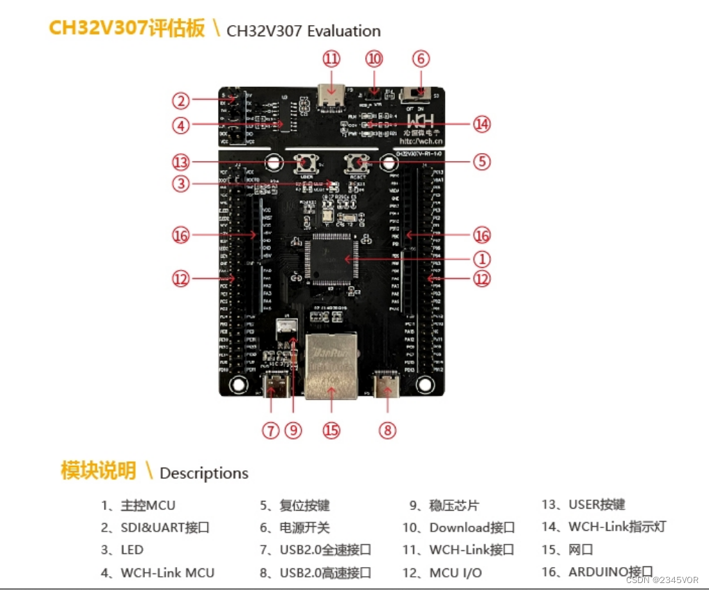
MCU:CH32V307VCT6,主频 144MHz,FLASH和RAM可配置
l 全双工或半双工的同步或异步通信
l NRZ 数据格式
l 分数波特率发生器,最高 9Mbps
l 可编程数据长度
l 可配置的停止位
l 支持 LIN,IrDA 编码器,智能卡
l 支持 DMA
l 多种中断源
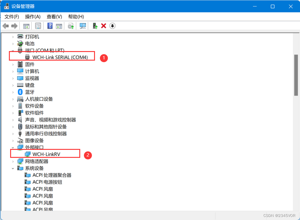
首先,应安装 CH32V307 评估板的驱动程序,打开设备管理器查看USB 端口和外部接口已准备就绪。
2. 软件配置
2.1 安装MounRiver Studio
环境搭建教程:https://blog.csdn.net/VOR234/article/details/128932474
3. UASRT项目测试
3.1 打开UASRT工程
评估板说明及参考例程:https://www.wch.cn/downloads/CH32V307EVT_ZIP.html
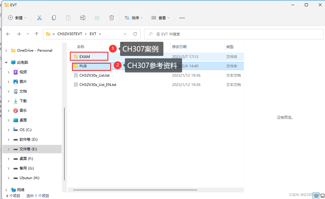
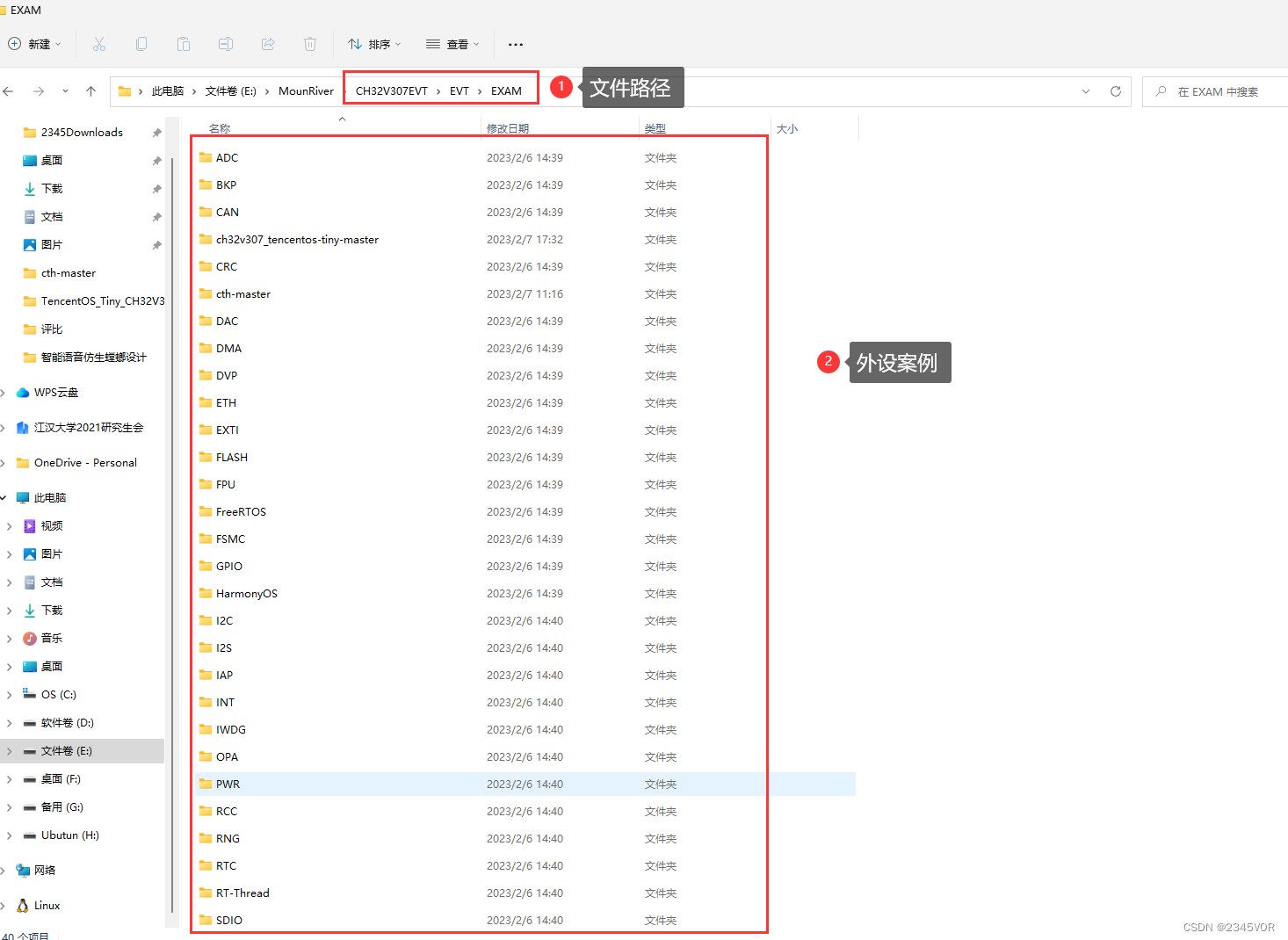
进入EXAM目录,就有对应的外设教程
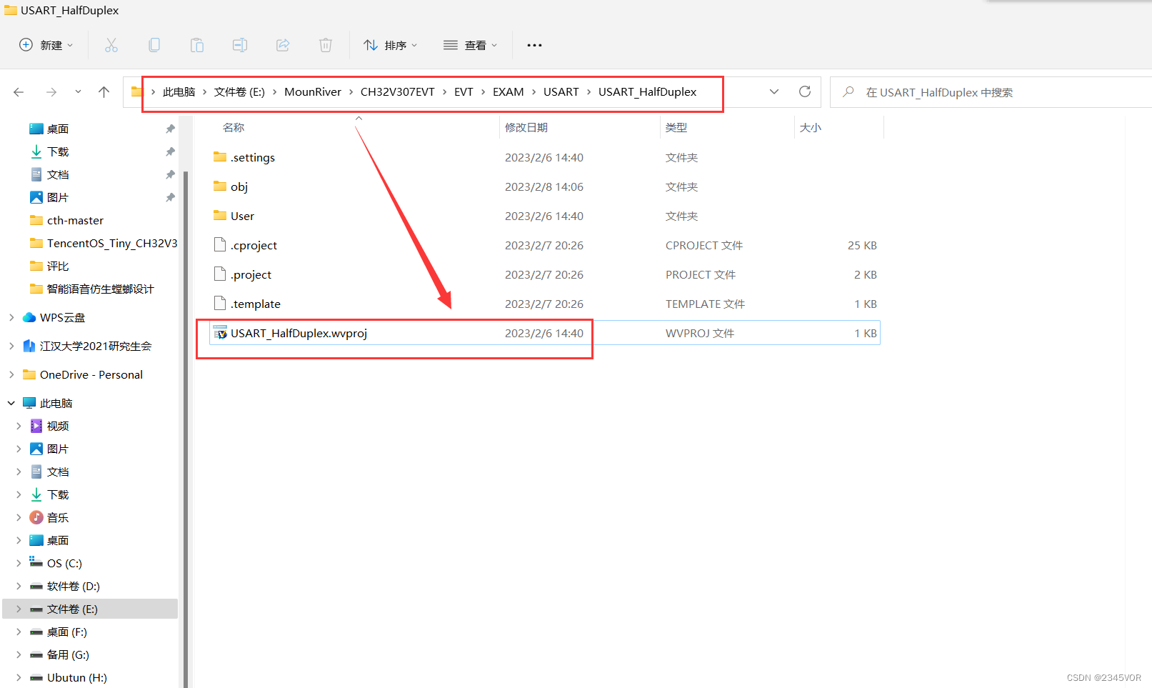
进入USART_HalfDuplex文件下,双击USART_HalfDuplex.wvproj,
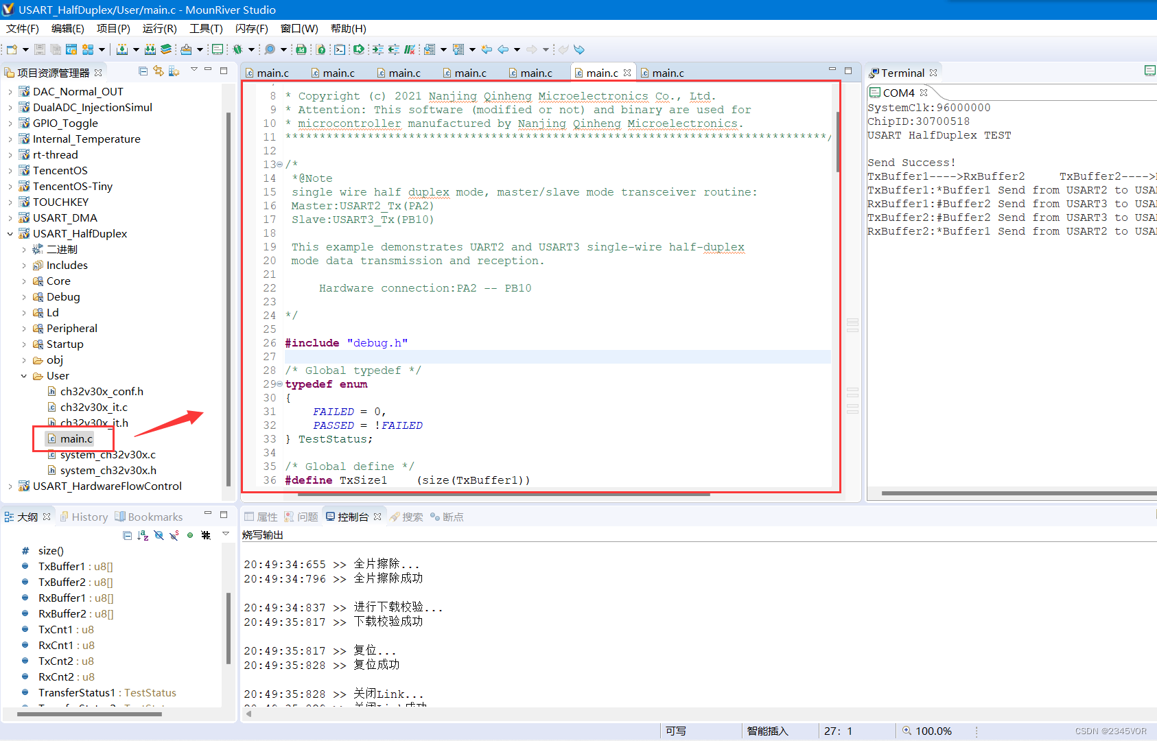
打开项目工程如下,main.c在user文件夹下
3.2 CH307串口发送数据到Arduino实验
修改CH307的main.c,杜邦线连接PB10(TX)--D2(RX);PB11(RX)--D3(TX)
/********************************** (C) COPYRIGHT *******************************
* File Name : main.c
* Author : WCH
* Version : V1.0.0
* Date : 2021/06/06
* Description : Main program body.
*********************************************************************************
* Copyright (c) 2021 Nanjing Qinheng Microelectronics Co., Ltd.
* Attention: This software (modified or not) and binary are used for
* microcontroller manufactured by Nanjing Qinheng Microelectronics.
*******************************************************************************/
/*
*@Note:采用CH307串口3与Arduino软串口收发通信
Hardware connection:PB10(TX)--D2(RX);PB11(RX)--D3(TX)
*/
#include "debug.h"
/* Global typedef */
typedef enum
{
FAILED = 0,
PASSED = !FAILED
} TestStatus;
/* Global define */
//#define RxSize1 (size(RxBuffer1))
#define TxSize1 (size(TxBuffer1))
#define RxSize1 256
#define size(a) (sizeof(a) / sizeof(*(a)))
/* Global Variable */
u8 TxBuffer1[] = "abcd"; /* Send by UART3 */
u8 RxBuffer1[RxSize1] = {0}; /* USART3 Using */
u8 TxCnt1 = 0, RxCnt1 = 0;
/*********************************************************************
* @fn USARTx_CFG
*
* @brief Initializes the USART3 peripheral.
*
* @return none
*/
void USARTx_CFG(void)
{
GPIO_InitTypeDef GPIO_InitStructure = {0};
USART_InitTypeDef USART_InitStructure = {0};
// NVIC_InitTypeDef NVIC_InitStructure = { 0 };
RCC_APB1PeriphClockCmd(RCC_APB1Periph_USART3, ENABLE);
RCC_APB2PeriphClockCmd(RCC_APB2Periph_GPIOB, ENABLE);
/* USART3 TX-->B.10 RX-->B.11 */
GPIO_InitStructure.GPIO_Pin = GPIO_Pin_11; /* Only Configure TX Pin */
GPIO_InitStructure.GPIO_Speed = GPIO_Speed_50MHz;
GPIO_InitStructure.GPIO_Mode = GPIO_Mode_AF_PP;
GPIO_Init(GPIOB, &GPIO_InitStructure);
GPIO_InitStructure.GPIO_Pin = GPIO_Pin_10; /* Only Configure TX Pin */
GPIO_Init(GPIOB, &GPIO_InitStructure);
USART_InitStructure.USART_BaudRate = 9600;
USART_InitStructure.USART_WordLength = USART_WordLength_8b;
USART_InitStructure.USART_StopBits = USART_StopBits_1;
USART_InitStructure.USART_Parity = USART_Parity_No;
USART_InitStructure.USART_HardwareFlowControl = USART_HardwareFlowControl_None;
USART_InitStructure.USART_Mode = USART_Mode_Tx | USART_Mode_Rx;
USART_Init(USART3, &USART_InitStructure);
USART_Cmd(USART3, ENABLE);
// NVIC_InitStructure.NVIC_IRQChannel = USART3_IRQn;
// NVIC_InitStructure.NVIC_IRQChannelPreemptionPriority = 1;
// NVIC_InitStructure.NVIC_IRQChannelSubPriority = 1;
// NVIC_InitStructure.NVIC_IRQChannelCmd = ENABLE;
// NVIC_Init(&NVIC_InitStructure);
//
// USART_Cmd(USART3, ENABLE);
}
/*********************************************************************
* @fn main
*
* @brief Main program.
*
* @return none
*/
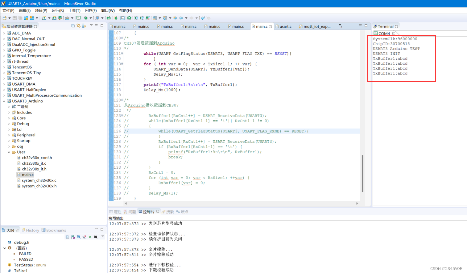
int main(void)
{
NVIC_PriorityGroupConfig(NVIC_PriorityGroup_2);
SystemCoreClockUpdate();
Delay_Init();
USART_Printf_Init(115200);
printf("SystemClk:%d\r\n", SystemCoreClock);
printf( "ChipID:%08x\r\n", DBGMCU_GetCHIPID() );
printf("USART3 Arduino TEST\r\n");
USARTx_CFG(); /* USART3 INIT */
printf("USART3 INIT\r\n");
while(1)
{
/*
CH307发送数据到Arduino
*/
while(USART_GetFlagStatus(USART3, USART_FLAG_TXE) == RESET){
}
for ( int var = 0; var < TxSize1-1; ++ var) {
USART_SendData(USART3, TxBuffer1[var]);
Delay_Ms(1);
}
printf("TxBuffer1:%s\r\n", TxBuffer1);
Delay_Ms(1000);
}
}
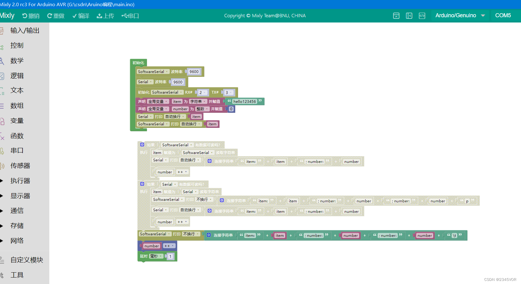
Arduino UNO 采用mixly编程
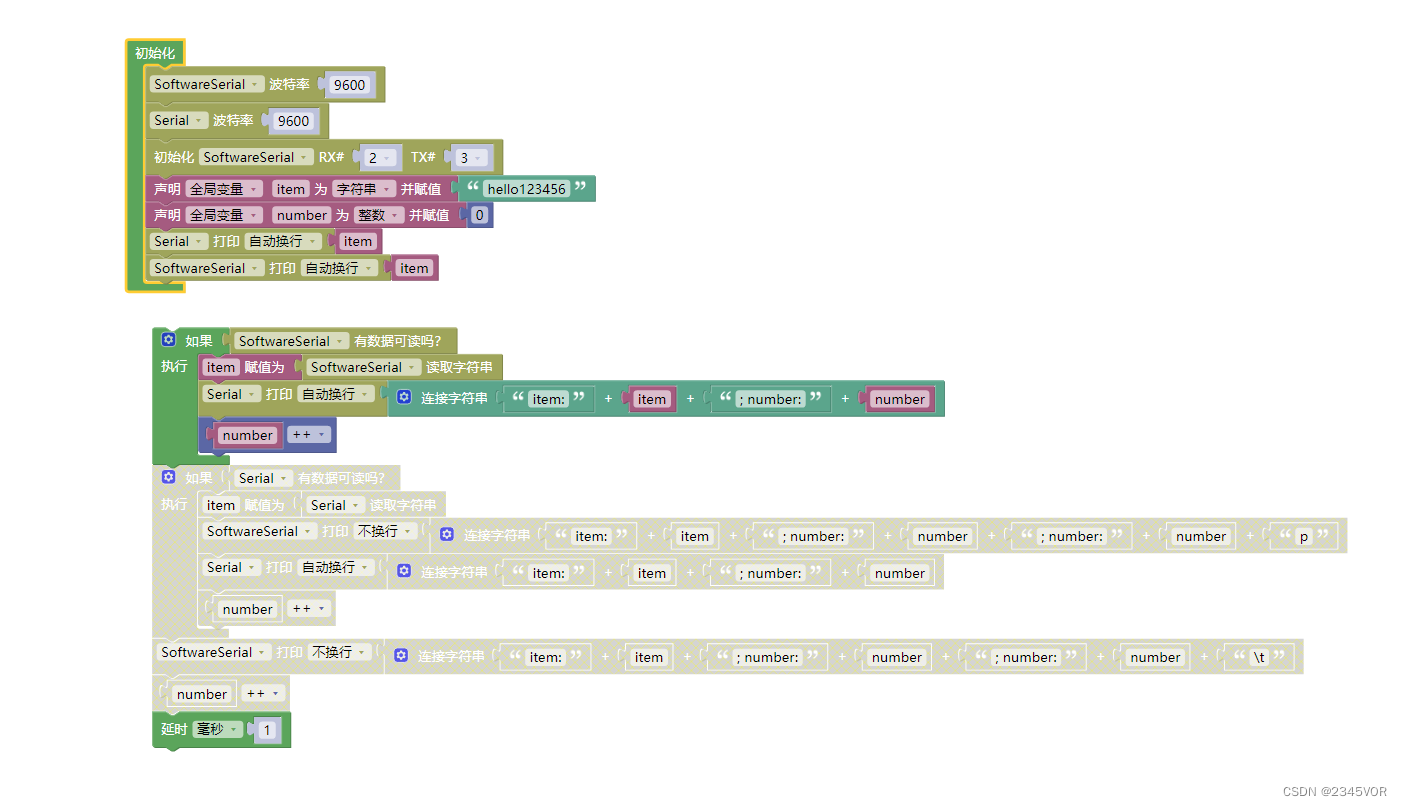
代码如下
#include <SoftwareSerial.h>

SoftwareSerial mySerial(2,3);
String item;
volatile int number;

void setup(){
  mySerial.begin(9600);
  Serial.begin(9600);
  item = "hello123456";
  number = 0;
  Serial.println(item);
  mySerial.println(item);
}

void loop(){
  if (mySerial.available() > 0) {
    item = mySerial.readString();
    Serial.println(String("item:") + String(item) + String("; number:") + String(number));
    number++;

  }
  delay(1);

}
实验效果
3.3 CH307串口接收数据Arduino实验
接线保持不变
修改CH307的main.c,杜邦线连接PB10(TX)--D2(RX);PB11(RX)--D3(TX)
/********************************** (C) COPYRIGHT *******************************
* File Name          : main.c
* Author             : WCH
* Version            : V1.0.0
* Date               : 2021/06/06
* Description        : Main program body.
*********************************************************************************
* Copyright (c) 2021 Nanjing Qinheng Microelectronics Co., Ltd.
* Attention: This software (modified or not) and binary are used for
* microcontroller manufactured by Nanjing Qinheng Microelectronics.
*******************************************************************************/

/*
 *@Note:采用CH307串口3与Arduino软串口收发通信
Hardware connection:PB10(TX)--D2(RX);PB11(RX)--D3(TX)

*/

#include "debug.h"

/* Global typedef */
typedef enum
{
    FAILED = 0,
    PASSED = !FAILED
} TestStatus;

/* Global define */
//#define RxSize1    (size(RxBuffer1))
#define TxSize1    (size(TxBuffer1))
#define RxSize1    256
#define size(a)    (sizeof(a) / sizeof(*(a)))

/* Global Variable */
u8 TxBuffer1[] = "abcd"; /* Send by UART3 */
u8 RxBuffer1[RxSize1] = {0};                                                   /* USART3 Using  */

u8 TxCnt1 = 0, RxCnt1 = 0;


/*********************************************************************
 * @fn      USARTx_CFG
 *
 * @brief   Initializes the USART3 peripheral.
 *
 * @return  none
 */
void USARTx_CFG(void)
{
    GPIO_InitTypeDef  GPIO_InitStructure = {0};
    USART_InitTypeDef USART_InitStructure = {0};
//    NVIC_InitTypeDef NVIC_InitStructure = { 0 };
    RCC_APB1PeriphClockCmd(RCC_APB1Periph_USART3, ENABLE);
    RCC_APB2PeriphClockCmd(RCC_APB2Periph_GPIOB, ENABLE);

    /* USART3 TX-->B.10  RX-->B.11 */
    GPIO_InitStructure.GPIO_Pin = GPIO_Pin_11; /* Only Configure TX Pin */
    GPIO_InitStructure.GPIO_Speed = GPIO_Speed_50MHz;
    GPIO_InitStructure.GPIO_Mode = GPIO_Mode_AF_PP;
    GPIO_Init(GPIOB, &GPIO_InitStructure);
    GPIO_InitStructure.GPIO_Pin = GPIO_Pin_10; /* Only Configure TX Pin */
    GPIO_Init(GPIOB, &GPIO_InitStructure);

    USART_InitStructure.USART_BaudRate = 9600;
    USART_InitStructure.USART_WordLength = USART_WordLength_8b;
    USART_InitStructure.USART_StopBits = USART_StopBits_1;
    USART_InitStructure.USART_Parity = USART_Parity_No;
    USART_InitStructure.USART_HardwareFlowControl = USART_HardwareFlowControl_None;
    USART_InitStructure.USART_Mode = USART_Mode_Tx | USART_Mode_Rx;


    USART_Init(USART3, &USART_InitStructure);
    USART_Cmd(USART3, ENABLE);
//    NVIC_InitStructure.NVIC_IRQChannel = USART3_IRQn;
//    NVIC_InitStructure.NVIC_IRQChannelPreemptionPriority = 1;
//    NVIC_InitStructure.NVIC_IRQChannelSubPriority = 1;
//    NVIC_InitStructure.NVIC_IRQChannelCmd = ENABLE;
//    NVIC_Init(&NVIC_InitStructure);
//
//    USART_Cmd(USART3, ENABLE);
}

/*********************************************************************
 * @fn      main
 *
 * @brief   Main program.
 *
 * @return  none
 */
int main(void)
{
    NVIC_PriorityGroupConfig(NVIC_PriorityGroup_2);
    SystemCoreClockUpdate();
    Delay_Init();
    USART_Printf_Init(115200);
    printf("SystemClk:%d\r\n", SystemCoreClock);
    printf( "ChipID:%08x\r\n", DBGMCU_GetCHIPID() );
    printf("USART3 Arduino TEST\r\n");
    USARTx_CFG(); /* USART3 INIT */
    printf("USART3 INIT\r\n");


    while(1)
    {
/*
CH307发送数据到Arduino
*/
//        while(USART_GetFlagStatus(USART3, USART_FLAG_TXE) == RESET){
//            }
//        for ( int var = 0;  var < TxSize1-1; ++ var) {
//            USART_SendData(USART3, TxBuffer1[var]);
//            Delay_Ms(1);
//        }
//        printf("TxBuffer1:%s\r\n", TxBuffer1);
//        Delay_Ms(1000);

/*
从Arduino接收数据到CH307
 */
        RxBuffer1[RxCnt1++] = USART_ReceiveData(USART3);
        while(RxBuffer1[RxCnt1-1] == 'i'|| RxCnt1-1 != 0)
        {
            while(USART_GetFlagStatus(USART3, USART_FLAG_RXNE) == RESET){
            }
            RxBuffer1[RxCnt1++] = USART_ReceiveData(USART3);
            if (RxBuffer1[RxCnt1-1] == '\t') {
                printf("RxBuffer1:%s\r\n", RxBuffer1);
                break;
            }
        }
        RxCnt1 = 0;
        for (int var = 0; var < RxSize1; ++var) {
            RxBuffer1[var] = 0;
        }
        Delay_Ms(1);
    }
}
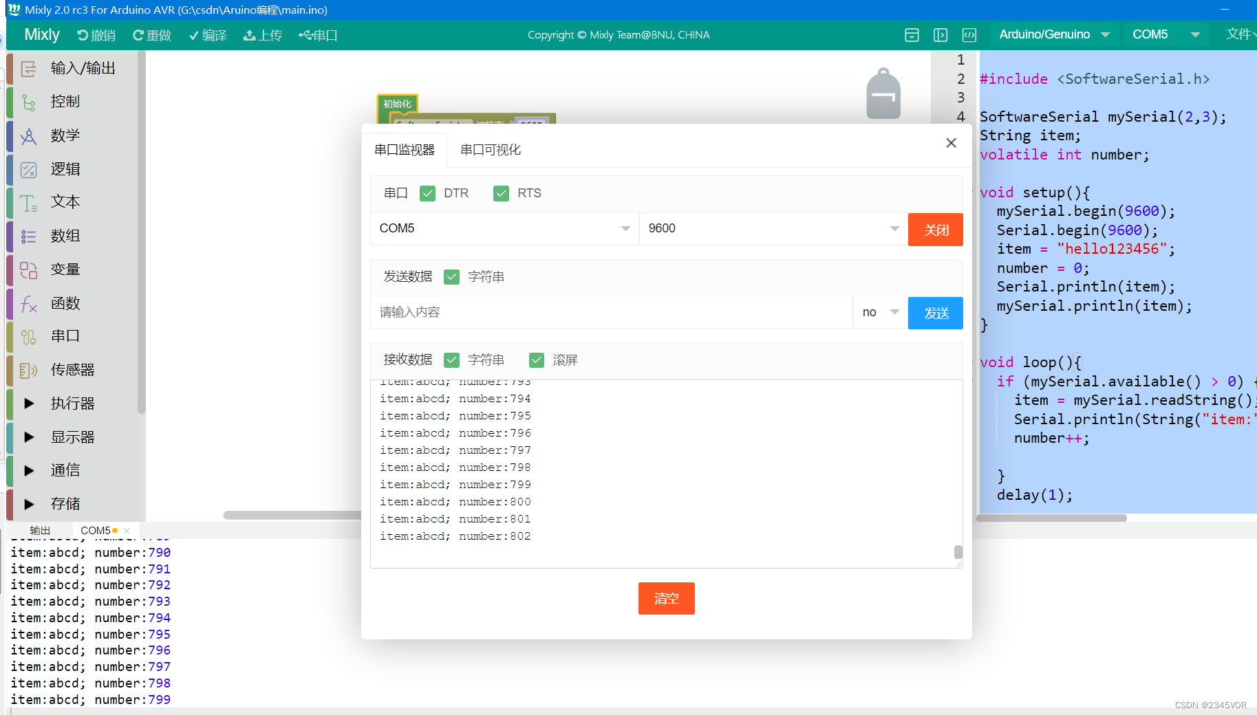
Arduino UNO 采用mixly编程
代码如下
#include <SoftwareSerial.h>

SoftwareSerial mySerial(2,3);
String item;
volatile int number;

void setup(){
  mySerial.begin(9600);
  Serial.begin(9600);
  item = "hello123456";
  number = 0;
  Serial.println(item);
  mySerial.println(item);
}

void loop(){
  mySerial.print(String("item:") + String(item) + String("; number:") + String(number) + String("; number:") + String(number) + String("\t"));
  number++;
  delay(1);

}
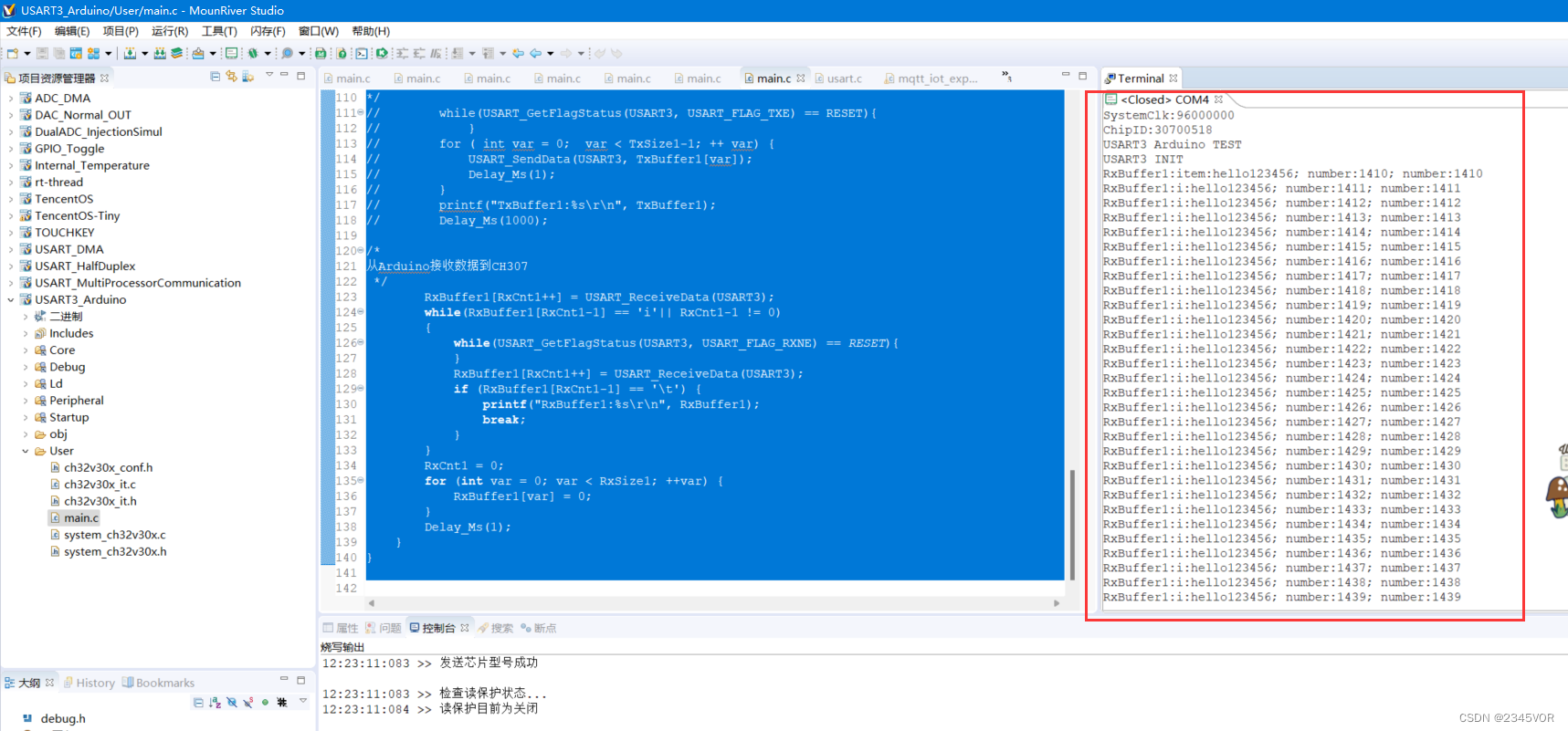
实验效果
5. 小结
🥳🥳🥳通过对这篇文章我们掌握了沁恒WCH CH32V307V-R1与Arduino的串口通讯,尝试与Arduino通讯做更加好玩的实验,进而丰富我们的生活。🛹🛹🛹从而实现对外部世界进行感知,充分认识这个有机与无机的环境,🥳🥳🥳科学地合理地进行创作和发挥效益,然后为人类社会发展贡献一点微薄之力。🤣🤣🤣
参考文献:
- CH32V307数据手册:https://www.wch.cn/downloads/CH32V20x_30xDS0_PDF.html
- CH32V307参考手册:https://www.wch.cn/downloads/CH32FV2x_V3xRM_PDF.html
- 评估板说明及参考例程:https://www.wch.cn/downloads/CH32V307EVT_ZIP.html
- CH343SER.ZIP串口地址:https://www.wch.cn/downloads/CH343SER_ZIP.html
- MRS最新V1.51版本安装包:www.mounriver.com
- 环境搭建教程:https://blog.csdn.net/VOR234/article/details/128932474
- 【沁恒WCH CH32V307V-R1开发板两路ADC读取实验】:https://blog.csdn.net/VOR234/article/details/128941074
- 【沁恒WCH CH32V307V-R1开发板读取板载温度实验】:https://blog.csdn.net/VOR234/article/details/128941832
- 【沁恒WCH CH32V307V-R1开发板输出DAC实验】:https://blog.csdn.net/VOR234/article/details/128942550
- 【沁恒WCH CH32V307V-R1的单线半双工模式串口通讯】:
https://blog.csdn.net/VOR234/article/details/128943395